The information given below is offered as a general guide only for typical 2 piece split body bolted construction ball valves. They are not specific to any particular valve or manufacturer.
OVERVIEW
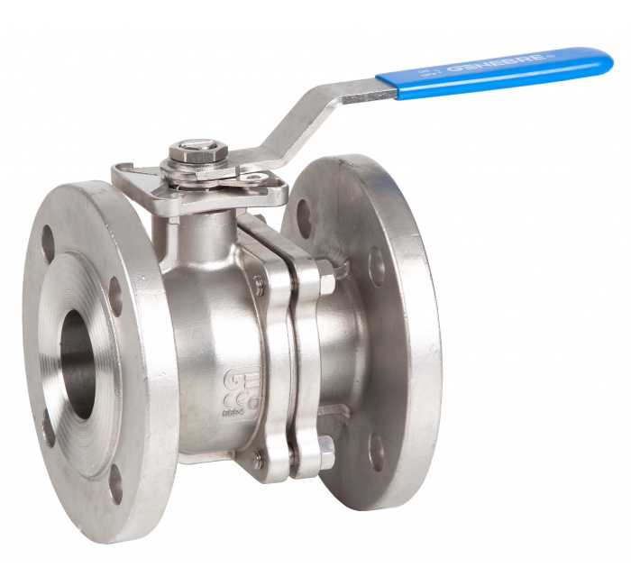
The 2 piece split body valve allows easy replacement of body gasket, seats and seals without the need for any specialist tools. They are a floating ball deign, the ball is free to move horizontally inside the valve body when induced to do so by the line pressure. The valve is capable of tight shut-off with flow in either direction or dead end, regardless of the position of the valve in the line. The downstream seat, opposite the pressurised side of a closed valve, carries the load exerted by the line pressure on the ball, whilst the upstream seat is subject to little load or wear. For this reason, it is sometimes possible to increase seat life by periodically turning the valve end for end in the line.
USE
Life of the valve can be maximised if the valve is used within its rated range in accordance with compatible flowing media, its pressure and temperature.
MANUAL OPERATION
To open or close the valve, turn the lever 1/4 turn (90 degrees) until it hits the physical stops.
In OPEN position, the valve lever is in line with the valve.
In CLOSED position, the lever is across the valve.
INSTALLATION
The valve may be fitted in any orientation. To prevent seat damage, the pipeline must be flushed, free of dirt, burrs, welding residues etc., and flange gasket seal faces cleaned, BEFORE installing the valve. These valves are heavy and adequate and, where required, safe lifting arrangements should be made prior to lifting the valve into the pipeline. Lift the valve into position and install using sound pipework fitting practice. System pressure tests (normally 1.5 times max working pressure) must be carried out with the valve in the OPEN position to prevent compression damage to the seats. If the valves contain silicone based lubricants from the assembly at the factory, and if silicone is unacceptable in your application, the valve should be stripped and degreased (solvent washed) before use.
MAINTENANCE – REPLACING SETS AND SEALS
- SAFETY – Use sound engineering practice and common sense when removing valves form pipelines – ensure the line is isolated and labelled as such with high visibility ‘Danger, men working, do not open’ (or signs required by local Health & Safety regulations) attached to the closed valves supplying the line, and drain the line before removing any flange bolts
- Remove flange bolts and nuts and lift the valve from the line taking great care to avoid scratching, scoring or damaging the flange gasket seal faces. These valves are heavy and adequate and safe lifting arrangements should always be made prior to lifting the valve out of line.
- Remove the lever securing nut and remove the lever and stop plate if fitted.
- Remove the body bolts using a correctly sized wrench. Separate and lift off the flanged end adapter.
- Remove the body seal.
- Lift out the ball, it is released by turning the valve to the closed position and extracting it in the direction of the removed flanged end adapter. Take great care not to scratch the surface of the ball as this may prevent correct sealing when the valve is reassembled.
- Using a soft headed hammer, tap the stem into the body cavity from where the ball was removed – the stem is blow-out proof and has to be removed from inside the body. Once the stem has been extracted, the stem O rings can easily be removed.
- Remove the downstream seat
- Clean and inspect all the metal parts and housing. It is not necessary to replace the ball and stem unless they show signs of abrasion or scoring. If they are scratched, scored or damaged, replace with new
- Reassemble in reverse order, fitting new seats, seals and packing. Light lubricating media, compatible with the intended media, will aid reassembly.
TESTING AFTER REASSEMBLY
- Secure a test fixture by means of a single mating flange with full bolting and a suitable gasket. Orient so that the seat being tested is facing upwards, and the added flange is facing downwards. Valve in closed position.
- Wearing eye and ear protectors, introduce 50 to 100psi of compressed air, partially open the valve then close, to ensure the cavity is pressurised. Check the stem seal is not leaking air, if a small leak can be heard, isolate then relieve the air pressure from the cavity by cracking the valve open, tighten the stem nut in 1/4 turn increments and re-test until the leak has stopped. Care must be taken not to over-tighten the stem nut as this adjustment affects the torque, and over-tightening is likely to cause problems with automatic operation. Pour water into the upper end to cover the ball and visually check for bubbles. If you see bubbles, the seat is leaking – pour the water off, operate the valve from open to closed several times, then redo the test. If the seat fails, relieve the air pressure completely, strip the valve and (a) check the parts were correctly installed and (b) that there is no damage to any of the parts. Correctly re-install parts if (a) or replace damaged parts if (b). Re-test. When this seat has passed (no bubbles), test the other seat.
- To check the other seat, switch the test flange to the opposite and, and test as above.
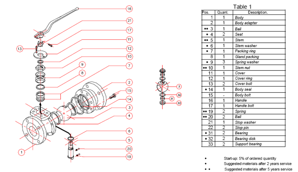
TYPICAL PARTS LIST AND EXPLODED VIEW